Profile Projectors / Shadowgraphs

An automated, instant measurement system that provides highly accurate and repeatable measurement data in seconds; simply place a part on the stage and push one button! Hundreds of critical features can be dimensioned on the part anywhere within the system's field of view. Built in automatic edge detection software allows for measurements to remain consistent among all operators and eliminate subjectivity. This user friendly tool can be used by anyone to compliment your quality control processes whether it is being used in a lab or out on the shop floor.
Products Lineup
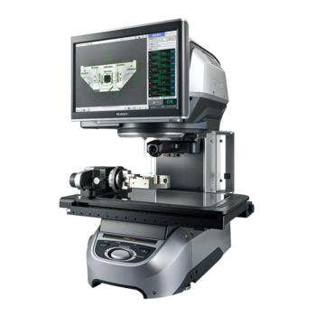
Capable of high-definition imaging, the IM-8000 Series Image Dimension Measurement System has triple the detection performance of conventional systems without sacrificing its simple operation; just place the part on the stage and press one button. With a 20-megapixel CMOS sensor and a new algorithm for stable edge detection, high-accuracy measurement on up to 300 features within seconds is now possible. A newly developed, optional automated rotary fixture allows for 360' multi-surface measurement on diverse part sizes and shapes. Achieve accurate and repeatable measurements instantly with its 'place and press' operation; this ensures consistent results regardless of operator experience. The fast, accurate, and easy-to-use interface of this product solve various measurement-related problems.
Features
Automatic Measurement on up to 300 Part Features in Seconds
Anyone can measure a part by simply placing it on the stage and pressing one button.
Regardless of operator skill, the unit provides accurate and repeatable measurements instantly.
01 | Place the part on the stage

02 | Press the button

03 | Measure 300 features in seconds

Measure Small, Large, and Three-dimensional Parts
The rotary unit coupled with advanced detection capability supports a wide range of shapes. Three-dimensional parts can be precisely measured.
Machined part
Screw and bolt
Pressed part
Injection moulded part
Connector
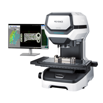
High-accuracy (±0.1 µm) measurement can be performed easily just by placing the part on the stage and pressing a button. Three measurement methods are available: high-accuracy image measurement, non-contact height measurement via a multi-colour laser, and contact measurement via a 3D touch probe. This product drastically reduces the dimensional measurement time of complex parts and ensures accurate measurements with no variations between results obtained by different operators.
Features
No Time-consuming Positioning or Coordinate Creation Required
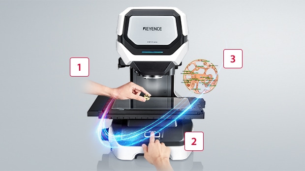
The location and orientation of parts placed on the stage are automatically detected. This eliminates the need for conventional labour-intensive positioning, creating coordinates, and preparing fixing jigs.
-
1STEP1 : Place
-
2STEP2 : Press
-
3STEP3 : Obtain results
Three Different Measurement Methods for Fast and Easy High-accuracy Measurement
Highly-accurate measurement along the X, Y, and Z axes.
-
1Touch probe : 3D measurement of three-dimensional parts
-
2Ultra-high-resolution camera : High-accuracy image measurement
-
3Multi-colour laser : Instant height measurement
Touch probe : 3D measurement of three-dimensional parts
Ultra-high-resolution camera : High-accuracy image measurement
Multi-colour laser : Instant height measurement
Measure up to 5000 Locations on up to 1000 Parts
Fast, simultaneous measurement is possible even when multiple parts are placed on the stage. There is also no need to use fixing jigs.

Large Low-Vibration Stage for High-Speed Measurement
The large stage has a maximum measuring area of 175 × 325 mm and a working height of 75 mm. The new design reduces the friction between the motor and feed screws as much as possible, allowing for quick and stable measurement without fixing the part in place.

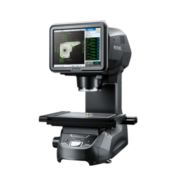
The LM Series High-Accuracy Instant Measurement System is an automated inspection system that can perform measurements to +/- 0.7 µm accuracy and +/- 0.1 µm repeatability at the push of a button. Similar to the IM Series, the unit has built-in edge detection with automatic focus and lighting. The unit also automatically records measurement data and creates detailed inspection reports. The image showcases our latest LM-1100 model which houses high-resolution double telecentric lenses for precision optical inspection and a large 9 x 5 inch field of view.
Features
Easier to Operate and with a Higher Degree of Accuracy
Operating conventional measuring microscopes and optical CMMs are challenging to master

- Difficult to take accurate measurements
- Difficult to use
- Measurement is time-consuming
The LM Series solves all of these conventional problems, allowing anyone to easily and accurately operate it

- ±0.1 µm high accuracy
- Simple operation for any user
- Measure instantly at the press of a button
Metal cutting parts
Allows clear checks of surface edge cuts.

Optical comparators are a type of optical measuring instrument. The measurement principle is similar to that of optical microscopes. The target is placed on the stage, and a light is shined on the target from underneath. This causes the target's profile, or shadow, to be projected on the screen. A telecentric optical system is used to enable accurate measurements.
Optical comparators were originally developed to inspect the outlines of targets. Models equipped with measurement functions appeared later. Some large optical comparators have screen diameters that exceed 1 m.
Optical comparators are also commonly known as a profile projector or shadowgraph.
Optical Comparator Principle (Telecentric Optical System)
A typical optical comparator illuminates from below and projects the shadow of the measuring object placed on the stage through a projection lens onto a projection screen. For this reason, it’s also known as a profile projector or shadowgraph.
At this time, the size of the projected image is an image magnified with a correct magnification from the measuring object, and the dimension of the measuring object is measured by measuring this image.
An optical system called a "telecentric optical system" is used in the optical comparator so that it can be projected with accurate magnification from any position on the stage. With a general lens, near objects look large and distant objects appear small, which allows you to judge perspective. Telecentric lenses, on the contrary, project the same size for near and far objects.
This telecentric lens allows you to cast the shadow of an object at the correct magnification without warping the image.

A: Projection screen, B: Projection lens, C: Movable stage, D: Stage movement handles (X and Y handles)
Precautions, Maintenance and Calibration
Conventional optical comparators require regular maintenance in order to continuously and accurately perform measurements. Maintenance is often performed onsite by a technician as the tool is generally too large to be sent off for regular maintenance.
In addition, regular calibration is required to confirm that the accuracy is as specified. An optical comparator’s calibration cycle is 6 months to 3 years. As with maintenance, calibration is generally performed locally.
Benefits of Profile Projectors / Shadowgraphs
A primary feature of optical comparators is that they have two dimensional measurement capabilities (X and Y directions), unlike hand tools such as micrometers, vernier calipers or height/depth gauges, which are limited to measurement in only one direction at a time.
The benefit is that it enables inspectors to double their output compared to the one direction hand tools. Operators can line up the lower left-hand corner of the image with the screen centreline to set up an origin point and get a simultaneous reading of both length and width helping to streamline inspection processes.
Optical comparators use a non-contact measurement that doesn't skew the measurement of flexible parts or damage sensitive parts. During the inspection process, nothing but light touches the part, so the part doesn't have any potential to warp or change shape.
A major benefit beyond part integrity is that non-contact gauges also eliminate the "feel factor" and resulting human error of hand gauges. With this subjectivity removed, companies see an improvement in the consistency of their measured values.
Companies can see cost benefits through optical comparator utilisation. One way is that they can reduce inspection time with optical comparators by measuring faster than conventional handheld gaging.
With the time saved and increased throughput, there can be a significant impact on profitability. Another cost saving comes in the form of hard gauges. By using optical methods more, you greatly reduce the wear of hard gauges. Also with more wear and need for periodic recertification, there's a requirement for additional substitute tools to use during these down periods which can now be eliminated with optical methods.
Place the object on the stage.
A scale is applied to the image projected enlarged on the screen to measure the dimensions. Alternatively, you can use the XY stage together and measure the dimensions from the amount of movement.
An optical comparator with a computerised calculation function, you can obtain various measurement results such as width, diameter, and angle by taking measurement points while moving the stage.
How to Measure a Length/Width
Place the object to be measured on the screen and adjust the height of the table to focus.
Next, align the orientation of the side you want to measure on the projected image with the orientation of the screen reference line, and adjust the value of the XY stage to 0.
Next, move the stage using the stage movement handle and align the other side of the projected image to be measured with the screen reference line.
At this time, the movement amount of the stage is displayed in each of the X and Y directions, so this value becomes the measured value. In the case of simple measurement in only one direction, the amount of movement in only the X or Y direction is used.
How to Measure a Radius /Diameter
Place the object to be measured on the screen and adjust the height of the table to focus.
Next, align the centre point of the circle on the projected image with the point where the screen reference line is public.
In the case of radius, take 0 points here and move the stage to check the movement amount at the point where the edge of the circle was at the centre of the stage. In case of diameter, move the stage once from here to the edge of the circle, take 0 point, and move to the opposite edge to check the amount of movement. In either case, it is common to measure in four directions in a cross shape.
It is also possible to measure by applying a concentrically graduated sheet called a "chart" to the screen.
In the case of an optical comparator with a calculation function, the diameter and radius are automatically calculated by taking three measurement points at the edge of the circle.
How to Measure Angles
There are several ways to measure the angle.
A method of checking the amount of rotation of the stage by rotating the stage in the θ direction by aligning the straight line of the projected image with the reference line of the screen.
There is a method of checking by putting a sheet called "chart" with fine scale like a protractor on the screen.
On an optical comparator with a calculation function, the angle is calculated by specifying two straight lines.
How to Use Overlays
There are several types of charts.
For measuring the diameter and radius, there are concentric circle marks, for measuring angles, there are radial marks, and for both. In addition, some of the scales are written in a grid to see the XY coordinate values. Both are placed on the screen and measured by matching them with the projected image.

Profile Projectors / Shadowgraphs Case Studies
Medical Industry
See case studies and white papers from medical companies that have implemented the IM Series automated optical comparator into their inspection processes. Many medical companies require FDA validation for use, so KEYENCE has made a normally difficult quick and easy with the help of their dedicated support staff. Example applications include medical tubing, stents, needles, vials, orthopedic screws, and more.
Automotive Industry
See case studies and white papers from automotive companies. Companies utilise the IM Series to meet the production part approval process (PPAP) design and specification requirements. Example applications include electrical connectors, springs/stampings, o-rings, gears, valves, etc.
Fixtures
Fixtures used for optical comparators are used to fix the object in place to be measured in the correct orientation. For example, a round object can be fixtured horizontally by clamping it down, or for fixing an object whose bottom surface is not flat in an orientation suitable for measurement.
There are various types of fixtures including clips, clamps and magnets.
Mylar Overlay Chart
The overlay chart is used by matching it with the measurement image projected on the screen. There are various types of charts. For example, those with a grid or concentric scale are generally used.
In addition, by overlaying the diagram chart in which the design value of the measurement target is magnified at the same magnification, it is possible to see how the contour of the design value differs from the actual measurement target by superimposing it on the projected image.
Surface Illumination
The optical comparator can not only illuminate from below and transmit light to create a shadow, but can also illuminate from above (lens side) to project outlines.
Even if the measurement target is difficult to measure with only the transmission (backlit) image, it is possible to measure it by using the epi-illumination.
Curtain
Blackout curtains are used to block light coming from outside. It is used for the purpose of projecting a shape more accurately by blocking ambient light.
Frequently Asked Questions About Profile Projectors / Shadowgraphs
Optical comparators are designed for visual two dimensional inspection. For this reason, a part would need to be reoriented and remeasured for three dimensional features. Another method would be to use a combination of tools such as an optical comparator, calipers/micrometers, and height gauges. For example; you can measure any two dimensional feature using the optical comparator, but then move the part over to a height gauge to get any required heights or depths. The final measured results can be manually written on a report or typed into an existing reporting platform.
KEYENCE's IM Series automated optical comparator measures up to 99 dimensions on a part in 3 seconds or less at the push of a button to +/- 2um accuracy. Once the part is measured, the system automatically records the data and creates an inspection report. Our latest unit has a built-in height gauge for Z axis measurements. When compared to a traditional optical comparator, companies see a significant reduction in inspection time, operator subjectivity and scrap and rework. The advantages in measurement speed, accuracy, and ease-of-use are immediate.
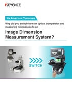
We asked our customers why they switched from conventional technologies to the IM Series Instant Measurement System. See how this system adds value to any inspection process.

See common optical comparator application examples measured on the IM Series Instant Measurement System. Application examples include: turned parts, machined parts, springs, stampings, fasteners, gaskets, etc.
![Q&A All About the IM Series IMAGE DIMENSION MEASUREMENT SYSTEM [Compilation]](/img/asset/AS_124472_L.jpg)
FAQ about the IM Series next-generation optical comparator and how it compared to conventional technology including vernier calipers, micrometers, and optical comparators.


