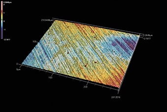
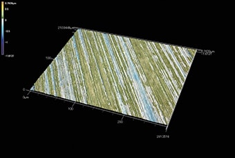
Quantifying Polished Surfaces
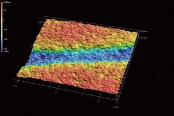
Polishing refers to the use of chemicals to make a surface smoother. Polishing is used in various industrial fields, such as lapping during the semiconductor manufacturing process.
This section introduces the basic characteristics of polishing and etching, along with application examples of 3D profile measurement systems.
- Lap Polishing
- Buff Polishing
- Electrolytic Polishing (Electropolishing)
- Chemical Polishing
- Wear Analysis Example
- Polishing Pad Profile Measurement Example
- Grindstone Profile Measurement Example
- Various Types of Etching
- Observing Polished Metal Structures
- Etching Amount Evaluation Example
- Example of Surface Roughness Measurement after Chemical Polishing
Lap Polishing
Place a target on a flat surface plate called a lapping machine, supply lapping powder (such as diamond, silicon carbide, or alumina) between the target and surface plate as an abrasive, and rotate the table to polish the surface of the target.
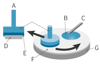
- A
- Side view
- B
- Slurry
- C
- Slurry feeder
- D
- Wafer
- E
- Carrier film
- F
- Polishing pad
- G
- Rotating table for polishing
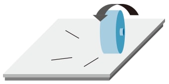
Buff Polishing
An abrasive compound is placed onto a wheel which presses against the surface to be polished. The wheel then spins to polish the surface.
Electrolytic Polishing (Electropolishing)
The sample is immersed in a solution and an electric current is passed through it so that the sample acts as the anode. Small amounts of iron or nickel atoms dissolve from the opposite pole to etch the sample. The polishing surface can be changed by changing the location of the cathode. This allows for fine control of the roughness with a small amount of etching.
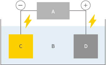
- A
- Power supply
- B
- Electrolyte
- C
- Opposite pole (Cathode)
- D
- Sample (Anode)
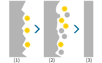
- (1) Before polishing
- Irregularities on the order of several micrometres
- (2) During polishing
- Surface irregularities being removed.
- (3) After polishing
- Smoothed
Electrolysation preferentially dissolves projections to smooth the surface.
Chemical Polishing
The sample is immersed in an acidic polishing solution to partially dissolve its surface. Unlike electropolishing, the polishing surface cannot be selected, so the entire surface in contact with the solution is etched uniformly.
| Electrolytic polishing (Electropolishing) | Chemical polishing | |
|---|---|---|
| Polishing amount |
Approx. 1 to 5 μm |
Approx. 1 to 20 μm |
| Available accuracy |
Sub-micron |
Micron |
| Electrode |
Required |
Not required |
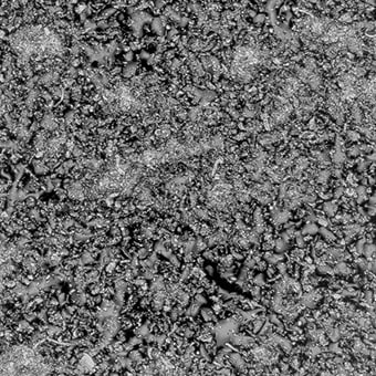
Wear Analysis Example
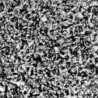
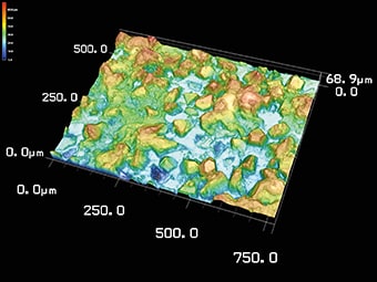
Analysing surface texture and the pattern of wear before and after etching makes it possible to classify and quantify the material arrangement and chemical composition conditions in detail, reducing wasted manufacturing costs.
Laser microscope
- Multiple data sets can be analysed simultaneously, under the same conditions.
- Surface-based evaluation allows for analysis of roughness, volume, and surface area.

Polishing Pad Profile Measurement Example
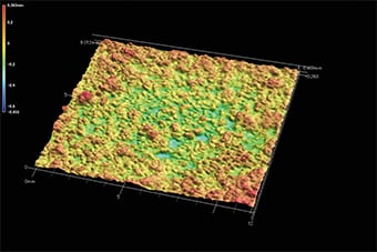
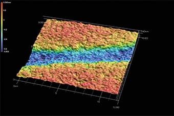
The surface conditions of polishing pads affect the flatness and uniformity of the polished sample.
Understanding the surface of polishing pads makes it possible to increase their quality and lifetime.
Laser microscope
- The measurement range is wide enough to evaluate the entire target with just one measurement.
- No sample prep required.
- The profile and irregularities of the surface can be quantified.
Grindstone Profile Measurement Example
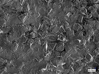
A grindstone contains abrasive grains of diamond plated on a base metal.
Understanding the profile of electroplated grindstones can lead to improved yield.
Laser microscope
- There is no limitation on the sample size, which allows for non-destructive evaluation.
- The profile and irregularities of the surface can be quantified.
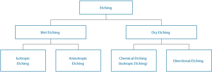
Various Types of Etching
Etching can be broadly divided into wet etching, which uses chemical solutions such as acids or alkali bases, and dry etching, which uses ions, gas, or radicals.
Wet etching
- Isotropic etching
-
At the mask opening, the target is etched radially at the same speed so that the area immediately below the mask is bored (side etching, undercut).

- A
- Mask
- Anisotropic etching
-
This method controls side etching to etch only in a specific direction by taking advantage of crystalline anisotropy.

- A
- Mask
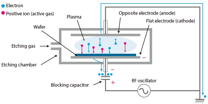
Dry etching
- Chemical etching (isotropic etching)
-
This method uses the chemical reaction between an ionised or radical reaction gas and the target.

- A
- Ion plasma
- B
- Resist
- C
- SiO2 or other oxide film (insulating material)
- D
- Silicon wafer
- E
- Films not covered by the resist are removed by the ions.
- Directional etching
-
This method etches the target by emitting ions or high-speed neutral particles with directional characteristics against it.
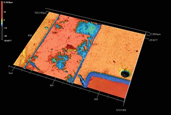
Observing Polished Metal Structures
Metal structures that could only be seen with an SEM can be observed. Measurement of the height of parts eroded by etching allows for evaluation of the structure.
Laser microscope
- The high image quality allows observation of metal structures that could previously only be seen with an SEM.
- Since the profile and roughness of the surface is quantified, no labour is needed for analysis.
- Measuring the height of the parts removed by etching allows for identification of the components of the structure.

Etching Amount Evaluation Example
The effect of etching can be quantified by evaluating the surface profile or surface roughness at different intervals or temperatures.
Laser microscope
- Differences in the surface profile can be quantified.
- Surface roughness can be evaluated without being influenced by stylus tip shape or wear.
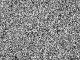
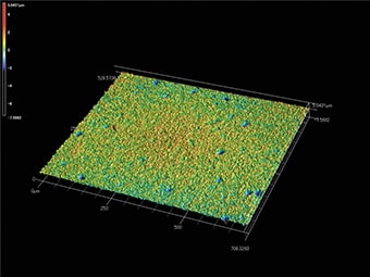
- Etching time
-
0 minute 
-
5 minutes 
-
10 minutes 
Example of Surface Roughness Measurement after Chemical Polishing
Measuring the surface roughness improves understanding of the effects of chemical polishing on the base material, which improves the yield rate.
Laser microscope
- 2D and 3D images are captured, allowing for quantitative and qualitative understanding of the surface.
- Measuring roughness across the entire surface ensures a high degree of reproducibility.
