Observation and Measurement of Moulds and Dies Using a Digital Microscope
Moulds and dies are tools that are essential to mass production in present-day manufacturing. Both are key elements in manufacturing―for example, moulds are used in injection moulding to shape resin as well as in casting, and dies are used in stamping. This section introduces observation and measurement examples of moulds and dies using a digital microscope.
- Advantages and disadvantages of using moulds/dies
- Types of moulds/dies
- Mould/die machining methods
- Observation and measurement examples of moulds and dies using a digital microscope
Advantages and disadvantages of using moulds/dies
- Advantages
-
- Fast mass production of products with the same shape.
- High-accuracy production with low variation.
- No special skills required with anyone able to perform operations easily.
- Minimal material waste and low processing costs.
- Disadvantages
-
- Mould/die fabrication can be costly and time-consuming.
- High level of skill and experience required for mould/die fabrication.
Types of moulds/dies
Moulds and dies are tools used to form and shape materials.
Dies are “open” in that they consist of top and bottom pieces that are not sealed.
Moulds, on the other hand, are “closed”, and materials such as metal and resin are poured into a cavity to form a finished product.
Dies
- Press dies
- Press dies are used to shape automobile bodies and other components. These are the most common type of die. Press dies can also be further categorised into punch dies, bending dies, and compression dies.
- Forging dies
- These dies are used to shape drive components for automobiles and other vehicles. The dies are used to hit a material and create a different shape. Parts requiring high strength are usually made with forging dies. There are two main forging methods: Hot forging, when the material is heated and softened before being struck, and cold forging, when the material is struck at room temperature.
Moulds
- Moulds for injection moulding
- These moulds are used for moulding plastic parts. A plastic material is heated in a heating cylinder and then pressurised and injected into a mould. The plastic then cools and solidifies.
- Moulds for die casting
- Die casting moulds are used for moulding by injecting molten aluminium, magnesium, or other material into a mould under high pressure. This makes it possible to mass-produce casting products with high accuracy and high-quality surface conditions at high speeds. The term “die casting” is generally used to refer to both the casting method and the moulded product.
- Casting moulds
- Casting is done by heating cast iron, aluminium alloys, copper, brass, or other materials to high temperatures until they melt, and then pouring the molten material into a mould. The mould used for casting is called a casting mould, and the resulting product is called a casting.
- Powder mould
- Powder moulds are used to form products by compressing and then hardening a metal powder.
Mould/die machining methods
- Cutting
- Moulds and dies can be machined using an edged tool to cut away the surface of a material. This cutting is most commonly done in a machining centre.
- Grinding
- Grinding bits can also be used to machine moulds and dies. This method makes it possible to machine hard materials that cannot be machined by cutting, including hardened steel and cemented carbide. Compared with cutting, this method allows for machining with higher accuracy and is commonly used for finishing. However, grinding also takes longer.
- Wire electrical discharge machining
- Wire electrical discharge machining is a method that uses brass wires to cut metal. With this method, machining is possible regardless of the hardness of the metal, enabling machining of hardened steel materials, cemented carbides, and other metals.
Observation and measurement examples of moulds and dies using a digital microscope
The latest examples of observation and measurement of moulds and dies using KEYENCE’s VHX Series 4K Digital Microscope are introduced below.
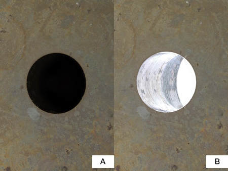
VHX-E20, 20×
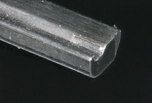
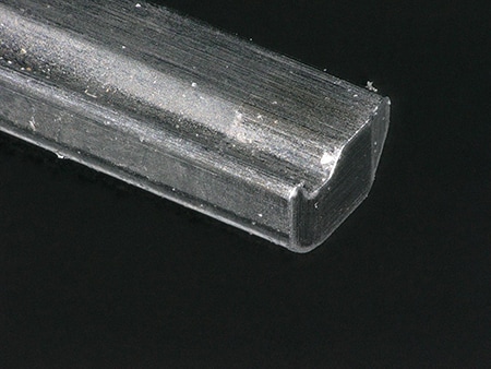
- A: Without backlight
- B: With backlight
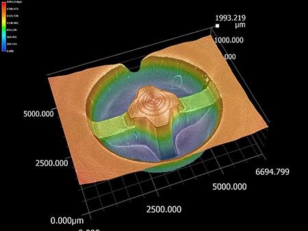
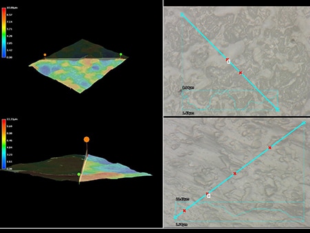
ZS-200, 1500×, coaxial illumination
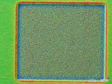
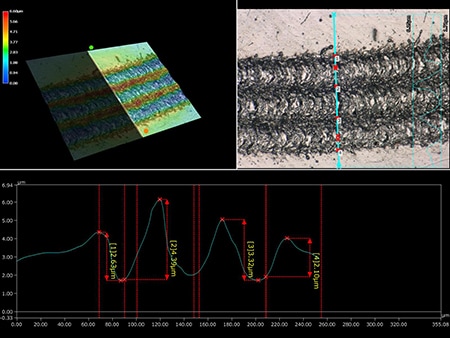
Managing wear is possible by measuring products in 3D.

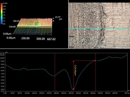
ZS-200, 500×, coaxial illumination
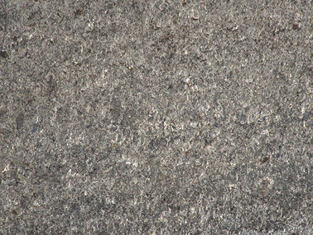
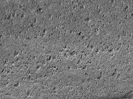
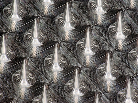
Optical Shadow Effect Mode image
Optical Shadow Effect Mode can be used to visualise microscopic irregularities.
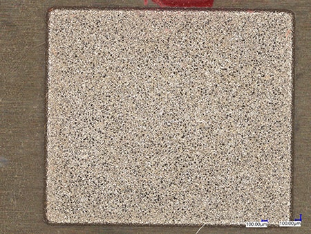
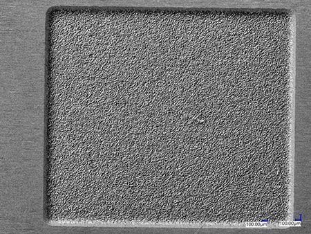
Optical Shadow Effect Mode image
Optical Shadow Effect Mode can be used to visualise satin surface patterns.
